Oak Bluffs, MA old classifieds archive and funnies > By Year
> 2007
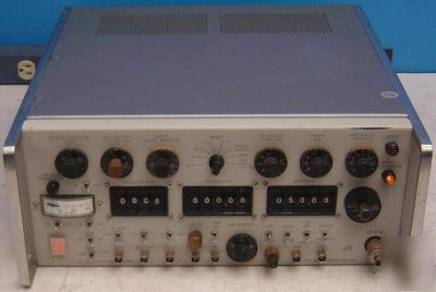
> Ifr atc-1200Y3 transponder & dme test set / simulator
Ifr atc-1200Y3 transponder & dme test set / simulator
IFR ATC-1200Y3 Transponder & DME Test Set / Simulator
Comes with a manual and what you see in the pictures. If you don't see it, you probably wont get it.
Specifications are from IFR and may vary slightly due to upgrades, options, or revisions this unit may or may not have.
The unit is guaranteed to work for 30-days.
The ATC-1200Y3 Test Set includes a built-in crystal-controlled signal generator, attenuator and modulators. It is designed to operate in conjunction with a dual trace oscilloscope to provide a complete bench test of the essential characteristics of civil ATC Transponders and DME sets. The ATC-1200YE system is capable of simulating a DME or Transponder ground station.
The Test Set includes all the RF hardware to test a DME or Transponder. This hardware includes a circulator to direct the transmitter power to a dummy load and power monitor, and to direct the signal generator to the receiver in the DME or Transponder. RF monitors are included for viewing the transmitter output and the input to the receiver. A diode switch in series with the signal generator is used to modular the signal generator to obtain over 80 dB on-off ratio for the transponder interrogation and over 85 dB on-off ratio in DME mode.
The ATC-1200Y3 Transponder/DME Test Set permits simulation of the ground station and airborne environment on the bench.
* Crystal-controlled, digital selection of distance and velocity
* 0.01 mile digital ranging steps from -1 to 999.89 NM
* 10 KT velocity steps from 0 to 9990 KTS
* Suppressor pulse output in XPDR and DME modes
* Measures peak power and transmitter frequency
* Crystal-controlled, leveled L Band generator
* All present and future DME channels
* Paired VOR (108.0 - 139.95 MHz) or direct frequency (950 - 1225 MHz) readout
The ATC-1200Y3 is a civil transponder and DME test instrument designed to meet the functional test requirements of a pulse test station. Only a high-quality, dual-trace oscilloscope and a counter are needed in addition to the ATC-1200Y3.
The ATC-1200Y3 is equally at home testing the simplest DME, or the sophisticated ARINC transponder or DME of latest design. Transponder tests feature interrogation in all modes including A/C, rapid setting of transmitter frequency and measurement of transmitter power. Receiver sensitivity checks are accurate and fast using the convenient front panel display of % reply.
DME tests include range measurements in 0.01 nautical mile (Nm) steps to 999.89 miles and equally accurate velocity measurements in 10 kt steps to 9990 kts. Both are crystal controlled. Tests to measure transmitter frequency, transmitter power, decoder window limits and receiver sensitivity are all front panel functions.
The built-in L-Band signal generator covers the spectrum of 950 - 1225 MHz. It may be operated in any of these three modes:
A) a crystal controlled, phased-locked generator with direct frequency readout,
B) a crystal controlled, phase-locked generator with paired VOR channel readout, or
C) as a continuously variable frequency generator from 950 - 1225 MHz. A CW function allows the test set to be used as a general purpose L-Band generator of high stability and an accurate output attenuator.
Transponder Section Specifications:
Interrogation Rate: Variable from 50 Hz to 5000 Hz. PRF Control accuracy +/- 5%.
Interrogation Modes: A/C, A, B, C, and D, per FAA TSO C-74a. Pulse spacing relative to leading edge of P1:
* Mode A/C: 8 µs +/- 0.06 µs, 21 µs +/- 0.08 µs
Transponder Pulse Characteristics: Pulse rise times should be 100 ns or less for P1, P2, and P3. When the leading edge of P2 is within 0.6 µs or less of the tailing edge of P1, the rise time of P2 degrades to greater than 100 ns. If P2 is within 0.3 µs of the trailing edge of P1, and P1 and P2 will deform. P2 may vanish.
Variable Pulse Spacing: P2 and P3 variable +/- 1.0 µs from each nominal position. Control accuracy +/- 0.05 µs at 0 setting and +/- 0.01 µs at +1 and -1 µs settings.
Variable Pulse Width: Variable width (of all three pulses simultaneously) from 0.4 µs to 1.2 µs. Control accuracy +/- 0.05 µs.
Side Lobe Suppression: Side Lob pulse spaced 2 µs relative to P1. Spacing accuracy +/- 0.05 µs. Variable in amplitude relative to P1 from -10 dB to +1 dB, control accuracy +/- .5 dB at +1 dB and 0 dB; and +/- 1 dB at -6 and -10 dB. P2 pulse may be turned off.
Pre Pulse: Selectable On or off by Front Panel switch. Equal in Amplitude and Width to P1 and P3. Time before P1 adjustable to 5 µs by the CAL 0 control
Calibration Mark Gen: Crystal controlled 1.0 µs or 1.45 µs time marks. Crystal tolerance +/- 0.1%. 1 µs frequency = 1 MHz. 1.45 µs frequency = .689650 MHz. Output pulse amplitude adjustable to 1V p-p with 51 ohm load.
TO: Negative sync pulses are provided approximately 5 µs prior to the leading edge of P1.
TD: Negative sync pulses are provided on the leading edge P3 for monitoring of al reply pulses.
Nominal amplitude is -15 V. Pulse width is 0.5 to 3 µs.
Transmitter Frequency Check: Transmitter frequency is measured by heterodyne method through diode mixers. Frequency settable to 500 kHz at 1090 MHz.
Transmitter RF Power: Measured by calibrated slide-back power meter. Power at any point of the reply pulse may be measured. Accuracy of power control is 12% at 2.5 kW and 15% at 50 watts.
Transponder % Reply: Meter readout 0 to 100%, Accuracy +/- 2%.
Suppressor Pulse: Coincident with P1 of interrogation pulse train. Pulse width is 50 µs, +/- 2 µs. Amplitude nominal 19 V, +/- 1 V.
Interrogation RF Pulse Risetime: Less than 100 ns. Overshoot 5% maximum.
Interrogation RF Pulse Decay Time: Less than 100 ns.
RF On/Off Ratio: 80 dB minimum, 85 dB typical
Squitter: DME pulse widths 3.5 µs, +/- 0.5 µs.
Ident System: Provides constant ident tone or coded IDENT signal. Tone frequency is 1350 Hz, +/- 1%. Ident equalizing pulse is spaced 100 µs from first pulse. Spacing accuracy: +/- 3 µs. IDENT signal is available every 30 seconds, +/- 2 sec of characters I-F-R.
TO: Negative sync pulses are provided approximately 1 µs after time of input interrogation.
TD: Sync Range - Negative sync pulses are provided (approx. 5 µs before) with each range reply pulse to permit viewing the reply pulses. Sync squitter - Negative sync pulses are provided at leading edge of P1 pulse to permit viewing squitter pulses.
Nominal amplitude of all sync pulses are -15 V. Pulse width is 2 to 15 µs.
Range System: Provides crystal controlled fixed range distances from -1 Nm to 999.89 Nm in 0.01 Nm selectable increments.
Range Accuracy: +/- 0.025 Nm, +/- 0.005% of range.
Velocity System: Crystal controlled velocity rates from 0 to 9990 KTS, in 10 KT selectable increments. Velocity accuracy 0.02%. Velocity range 0 to 300 N.M. with meter readout. Range readout accuracy +/- 5 N.M. Electrical slewing 0 to 300 N.M. in approximately 6 sec.
Note: Due to discrete range steps in Velocity mode of 0.01 mile and to range jitter of .01 mile max, the maximum range uncertainty is .02 mile when measuring velocity on a time interval counter. If the range-change verses time measurement is made at 1000 knots for 60 seconds, the maximum velocity error due to the .02 mile uncertainty is +/- 0.12%. See table below.
A. When measuring at a 60 second time interval:
B. When measuring at a 30 second time interval:
C. When measuring at a 10 second time interval:
Percent Reply: Random Reply elimination with average count down rate variable from 20% to 100% replies. Control accuracy +/- 5%.
Tacan Simulation: Simulation only by amplitude modulating all output pulses with 60 Hz. Modulation level variable from 0 to 50%.
Suppressor Pulse: Output rate is a constant value controlled by Squitter PRF control. Pulse width is 50 µs +/- 2 µs . Amplitude nominal 19 V +/- 1 V.
R-NAV Pulses: P1 at time of interrogation; P2 at time of reply. Pulse spacing at 0 nm is 50 µs in X ch, +/- 0.25 µs, and 56 µs in Y ch, +/- 0.25 µs. Pulse width is 7 µs, +/- 3 µs, amplitude 15 V, +/- 3 V.
Decoded: An input decoded is incorporated which will accept input pulse pairs only with spacings between: in X ch - 8.5 µs to 15.5 µs +/- 0.5 µs. in Y ch - 33.5 µs to 38.5 µs +/- 1.0 µs.
DME Pulse Widths Characteristics:
DME pulse widths should be 3.5 µs +/- 0.5 µs when on a frequency of 1030 MHz. For "X" channel operation, the spacing cannot be operated in the -4 µs, -5 µs or -6 µs position without severe pulse distortion because P1 and P2 are being overlapped.
In X channel 12 µs +/- 0.2 µs. In Y channel 30 µs +/- 0.2 µs. Pulse spacing is adjustable from nominal 12 or 30 µs in +0.5, +/- 3.0, +/- 4.0, +/- 5.0 and +/- 6.0 µs steps. Accuracy of incremental spacing is +/- 0.2 µs. X or Y channel spacing by VOR frequency.
Echo Pulse: Echo Pulse pair injected 30 nm from time to interrogation. Range accuracy of echo pulses +/- 0.5 nm. Echo pulse amplitude variable from -10 dB to +1 dB, control accuracy +/- 0.5 dB at -10 dB, -6 dB, 0 dB and +1 dB, relative to normal reply pulse. Normal reply pulses cannot be used within +/- 5 nm of echo pulses. Echo pulse pair may be turned off. All output pulses are square instead of Gaussian shaped when the echo system is activated.
PRF Measurement: Interrogation rate of DME read out on meter on 0-30 and 0-300 PRF ranges. PRF accuracy +/- 3% full scale.
Modulator Pulse Output: Gaussian-shaped reply pulse pair timed within +/- 3 µs of RF reply pulses. Amplitude adjustable from 0 V to -10.5 VDC restored to peak of 0 V. Spacing same as RF pulses.
Transmitter Frequency Check: Transmitter frequency is measured by heterodyne method through diode mixers. Used only to verify the proper on-channel frequency to +/- 1 MHz.
Transmitter RF Power: Measured by calibrated slide-back power meter. Power at any point of the interrogate pulse may be measured. Accuracy of power control is 12% at 2.5 kW and 15% at 50 watts.
DME RF Pulse Output: Gaussian-shaped reply pulses 3.5 µs +/- 0.50 µs wide at 50% amplitude point.
RF On/Off Ratio: 85 dB minimum, 95 dB typical.
Signal Generator Section Specifications:
Frequency: 950 MHz to 1225 MHz
1) In GHz position, the front panel frequency switch indicates generator frequency directly in MHz providing decimal point is considered invalid. Phase lock range typically 960 MHz to 1215 MHz. Frequency selected in 1 MHz increments. Output frequency accuracy +/- .008%. DME spacing always X ch in GHz mode.
2) Paired VOR channel readout: Front panel frequencies switch indicates VOR frequencies from 108.00 to 117.95 MHz, and 133.30 to 135.95 MHz selectable in 50 kHz increments. Output frequency from 962 MHz to 1213 MHz paired to VOR channels. Phase lock range 962 to 1213 MHz. Output frequency +/- .008%. All XXX.00 channels select X ch. spacing; all XXX.05 channels select Y ch. spacing.
3) Variable Frequency: Range 950 MHz to 1225 MHz, Drift rate typically less than 2.0 MHz in a one-hour period. An external counter capable of counting 3.25 MHz can display the output frequency. Add 9 MHz to the counter reading and multiply the sum by 100 to obtain the output frequency.
Output Leveling: For sets prior to S/N 1500, RF output leveled to +/- 2.0 dB for any one attenuator setting over frequency range 962 to 1213 MHz.
RF Output Level: Continuously variable from 0 dBm to -110 dBm. Attenuator accuracy +/- 1.5 dBm from -30 dBm to -100 dBm referenced to output leveling. Output level is calibrated at XMTR/REC Connector (36). Harmonic content of output is 70 dB down from attenuator is non-linear from 0 dBm to -30 dBm. Use of attenuator calibration curve is mandatory for this region of operation.
AC Power Requirements: 105 to 120 VAC or 220 to 250 VAC, 50 to 400 Hz. Cooling fan 50/60 Hz only.
Weight: 36 lbs. - does not include packaging!
Dimensions: 7.5" H x 16.75" W x 18.375" D - does not include packaging!