Oak Bluffs, MA old classifieds archive and funnies > Recently Submitted
> Mitsubishi compact inverter (drive)
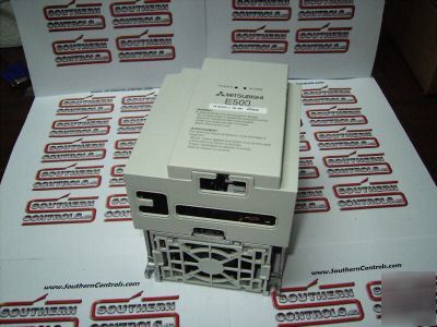
Mitsubishi compact inverter (drive)
The cost-effective variable speed control solution for general purpose applications.
* Up to 10 Hp at 240 VAC, 480 and 600 VAC
* Advanced Magnetic Flux Vector Control
* 50°C maximum ambient temperature
* RS-485 serial communication (standard)
* Selectable cooling fan operation mode
* Adjustable carrier frequency (0.7kHz to 14.5kHz)
* Optional keypad interface (FR-PA02-02)
* Compatible with FR-PU04 user interface
* UL & cUL listed / CE marked
* Available configuration software for Windows® 95 / 98
* Open-network communication options
* Profibus DP (400V and 600V only)
1-Phase 100 – 115 VAC Input / 3-Phase 230 VAC Output
200 – 240 VAC Input / 3-Phase 200 – 240 VAC Output
3-Phase 380 – 480 VAC Input / Output
3-Phase 575 – 600 VAC Input / Output
E500 Series General Specifications
Soft-PWM control / high carrier frequency PWM control can be selected.
V / F control or general-purpose magnetic flux vector control can be selected.
0.2 to 400Hz (starting frequency variable between 0 and 60Hz)
Across terminals 2-5: 1/500 of maximum set frequency (5 VDC input),
1/1000 (10 VDC, 4-20mADC input).
0.01Hz (less than 100Hz), 0.1Hz (100Hz or more) when digital setting
is made using the control panel.
Within ±0.5% of maximum output frequency (25°C ±10°C) / 59°Fto 95°F.
Within 0.01% of set output frequency when setting is made from control panel.
Base frequency set as required between 0 and 400Hz. Constant torque
or variable torque pattern can be selected.
150% or more (at 1Hz), 200% or more (at 3Hz) when general-purpose
magnetic flux vector control or slip compensation is selected.
Manual torque boost, 0 to 30% may be set.
0.01, 0.1 to 3600 sec. (acceleration and deceleration can be set individually),
linear or S-pattern acceleration/deceleration mode can be selected.
0.1K, 0.2K ... 150% or more, 0.4K, 0.75K ... 100% or more, 1.5K ... 50%
or more, 2.2K, 3.7K, 5.5K, 7.5K ... 20% or more *1
Operation frequency (0 to 120Hz), operation time (0 to 10 s), operation voltage
Stall Prevention Operation Level
Operation current level can be set (0 to 200% variable), presence or absence
Operation level is fixed, presence or absence can be selected.
Operation level is fixed, presence or absence can be selected.
0 to 5 VDC, 0 to 10 VDC, 4 to 20mADC.
Entered from control panel (FR-PA02-02).
Forward and reverse rotation, start signal automatic self-holding input
(3-wire input) can be selected.
Used to reset alarm output provided when protective function is activated.
Up to 15 speeds can be selected. (Each speed can be set between 0 and 400Hz,
running speed can be changed during operation from the control panel.)
Used to select second functions (acceleration time, deceleration time,
torque boost, frequency, electronic overcurrent protection).
Instantaneous shut-off of inverter output (frequency, voltage).
Used to select input of frequency setting signal 4 to 20mADC (terminal 4).
Used to select start signal automatic self-holding input. (3-wire input)
Thermal relay contact input for use when the inverter is stopped by the
PU Operation-External Operation
Used to switch between PU operation and external operation from outside the inverter.
Used to switch between V/F control and general-purpose magnetic flux vector
Maximum/minimum frequency setting, frequency jump operation,
external thermal relay input selection, automatic restart operation after
instantaneous power failure, forward/reverse rotation prevention, slip
compensation, operation mode selection, off-line
2 open collector output signals can be selected from inverter running,
up to frequency, frequency detection, overload alarm, zero current detection,
output current detection, PID upper limit, PID lower limit, PID forward/reverse
rotation, operation ready, minor fault and alram, and 1 contact output
(230 VAC 0.3A, 30 VDC 0.3A) can be selected.
1 signal can be selected from output frequency, motor current and output voltage.
Pulse train output (1440 pulses/second/full scale).
Output voltage, output current, set frequency, running.
Alarm definition is displayed when protective function is activated.
4 alarm definitions are stored.
Protective and Warning Functions
Overcurrent shut-off (during acceleration, deceleration, constant speed),
regenerative overvoltage shut-off, undervoltage *2, instantaneous power
failure *2, overload shut-off (electronic overcurrent protection),
brake transistor alarm, output short circut, stall prevention, breake resistor
overheat protection, fan overheat, fan failure *4, parameter error,
PU disconnection, ground fault protection.
Constant torque: -10°C to +50°C (non-freezing) 14°F to 122°F
90%RH or less (non-condensing)
-20°C to +65°C / -4°F to 149°F *3
Indoors, no corrosive and flammable gases, oil mist, dust and dirt.
Maximum 1000m (3300 ft.) above sea level for standard operation.
After that derate by 3% for every extra 500m up to 2500m (91%).
5.9 m/s² (0.6G max.) based on JIS C 0911.
1. The braking torque torque indicated is a short-duration average torque (which varies with motor loss) when the motor alone is
decelerated from 60Hz in the shortest time and is not a continuous regenerative torque. When the motor is decelerated
from the frequency higher than the base frequency, the average deceleration torque will reduce. Since the inverter does not
contain a brake resistor, use the optional brake resistor when regenerative energy is large. (The optional brake resistor cannot
be used with 0.1K and 0.2K.) A brake unit (BU) may also be used.
2. When undervoltage or instantaneous power failure has occurred, alarm display or alarm output is not provided but the
inverter itself is protected. Overcurrent, regenerative overvoltage or other protection may be activated at power restoration
according to the operating status (load size, etc.).
3. Temperature applicable for a short period in transit, etc.
4. Not provided for the FR-E520-0.1K to 0.4K and FR-E510W-0.1K to 0.75K which are not equipped with a cooling fan.
For use only on FR-PA02-02 and FR-CB20x
E540, E560 DeviceNet Interface
Plug-in Option. Not for use with E520 or E510W.
E540, E560 Profibus DP Interface
Plug-in Option. Not for use with E520 or E510W.
Plug-in Option. Not for use with E520 or E510W.
Plug-in Option. Not for use with E520 or E510W.
E520 with Built-In DeviceNet Interface
Same ratings as -NA version. Deeper by 19.6 mm than -NA.
E520 with Built-In CC-Link Interface
Same ratings as -NA version. Deeper by 19.6 mm than -NA.
FR-E520/E540/E510W Instruction Manual
FR-E520-KN CC-Link Instruction Manual
FR-A500 / E500 Technical Manual
FR-E5NC, CC-Link Instruction Manual
FR-E5ND, DeviceNet Instruction Manual
FR-E5NP, Profibus Instruction Manual
FR-E520-KND, DeviceNet Instruction Manual
Programming and Diagnostic Software
All Mitsubishi Electric VFD’s have some inherent braking capability. During controlled deceleration, motor regenerative losses are dissipated in the motor, wire, and VFD circuitry. The built-in DC injection braking allows for low speed braking and stopping.
When the above capabilities are inadequate for an application, it is necessary to add a power transistor brake unit and resistor unit in series across the DC bus.
Motor regeneration causes the DC?bus voltage to increase, and when the voltage exceeds a specified threshold, the transistor turns on to pass current through the
resistor. Motor kinetic energy is converted to heat energy. VFD overcurrent and overvoltage protective circuits are active at all times, and will fault-trip the VFD if the brake size is inadequate.
Two main factors must be considered when sizing the brake, the effective duty cycle (%ED) and the short time duty rating. The effective duty cycle is increased when
an external resistor is added. It is preferable to profile the effective duty cycle of the units of time. With this information, the short time duty is known and the %ED can be calculated, as shown in the below example.
%ED = Braking time / total time for complete operating cycle *100
5 sec: Acceleration time to reach set speed
60 sec: Run time at set speed
3 sec: Deceleration time to come to a complete stop
12 sec: Time period motor remains stopped
%ED = 3 / (5 + 60 + 3 + 12) * 100 = 3.6%
The tables shown assume 100% brake torque, when brake torque is represented by its percentage to the rated torque of the applied motor.
Torque (kg.m) = 974 * Power (kW) / Speed (rpm).
Dynamic Braking Unit for 230 VAC • Braking Torque = 100%
Dynamic Braking Unit for 460-480 VAC • Braking torque = 100%
1. The FR-A520-0.4K to 7.5K and FR-V520 - 1.5K to 15K have a built-in braking transistor.
2. Optional brake resistor is only available for FR-E520-0.4K-NA and higher.
This filter is connected to the input of the drive and helps to reduce radiated noise in the radio frequencies.
Provides a toroid for line noise reduction.
This attachment allows the E500 Series inverter to mount on a 35mm DIN rail.
Installation Interchange Attachment
This attachment allows the E500 Series inverter to be mounted using the installation holes from the previous series VFDs.
Installation Model E500 Series
E500 Installation Interchange Attachment
This attachment allows the E500 Series inverter to be mounted at a 90° angle so that the depth is reduced to 80 mm.
E500 Series Watt Loss and Efficiency Data
240VAC 3-Phase Input or 1-Phase Input
1. The amount of heat generated by the inverter is based on one inverter connected to one motor of the same capacity.
2. The amount of heat generated in the above table is the amount of heat generated when the inverter is operated at it's rated current.
3. The amount of heat generated will decrease according to the motor load and usage (duty).
This attachment allows the VFD to be mounted onto the filter.
These units are surplus stock and are new in the factory box unless otherwise described. All units come with a 7 day DOA warranty and can be exchanged for another unit if avaliable. If you have any questions or need any help please give us a call at (***)-272-9895 or visit our website at . Representative Photo.Item you received may vary. Please feel free to make an offer all offers will be seriously entertained